Gear shapers: description, characteristics, types and operating mode
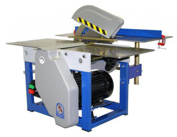
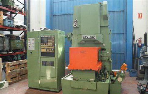
Gear shapers in modern designThey are equipped with a rigid structure and a powerful electric motor. Vertical assembly units are also equipped with hydrostatic bearings, a cooling system and a slotting spindle. High performance is due to the possibility of increasing the speed of the working part to two thousand revolutions per minute. Functional and technical parameters of the models are expanded due to the CNC, as well as the movable spindle carriage, which allows changing the position of the dolly element in relation to the machined gear.
Varieties
Gear shapers are divided into three main types:
- Modifications with a moveable table in the horizontal plane, allowing to produce feed to the infeed. Also in its design is a fixed stand.
- Variants with a fixed table and a rack, moved horizontally and serving to transport the tool at the time of infeed.
- Models with a static table, horizontally moving rack and carriage, capable of pushing vertically the grooving tip, changing the position of its stroke.
Automated unit with fixed tablehas more advantages than its counterparts. For the possibility of making conical teeth one of the axes of the tool is mounted at a certain angle. On machines used in mass production, there is an intermediate plate, placed under a vertical rack. Universal modifications are equipped with the ability to tilt the table or rack in a range of 10 degrees.
Gear-cutting machines: CNC models
In a software-controlled modification, complexThe kinematic schemes have been replaced by separate engines for the main moving of the cutting tool and the adjustment of the unit along the axes. In the horizontal plane, the rack moves to change the diameter of the machining of parts with internal and external gearing, as well as radial feed.
The rack moves along the axes in the case of a radialtapping of the grooving part at an angle and finishing of special gear profiles. Moving the carriage in a vertical plane causes the processing area to vary in height. The spindle drive of an independent type provides the required rotation of the workpiece, and the programmable interaction enables the achievement of maximum accuracy by running-in.
Technical capabilities
Gear-cutting machines with CNC have the abilitychanges in mobility of the stem. Retraction of the breaker on the reverse stroke is performed by means of a backward displacement, which simplifies the construction of the equipment, increasing its rigidity. Correct the direction of the tooth can be with a slight slope of the working part.
Thanks to the design features of the models withCNC, there is the possibility of expanding the functionality, as well as compliance with the accuracy of manufacturing in accordance with GOST 1643-81. The crowns of the toothed type have an identical module and are processed by a single grooving tool. The sequence of manipulations in one pass increases the productivity and accuracy of the placement of the rims.
Principle of operation
Technical Characteristics of Gear Shapersallow to carry out the process of cutting by reciprocating the working part. Semiautomatic units have a vertical layout. Installation at the center-to-center distance and insertion of the tooth at the required depth is adjusted using a table moved by the hydraulic cylinder. The equipment can function in the adjustment and semi-automatic mode with the possibility of reusable finishing of products.

Changing the circular feed allows electricalDC motor. It receives power from a special amplifier with an automatic switch that cycles the processing of the workpiece. With the three-speed motor of the main drive, the double movement of the tool can be performed per minute. The radial tapping is carried out by the work of a wedge slider, moved by a hydraulic cylinder. The total range of tie-in is carried out through the stops, and the idling at idle speed is by means of a spindle. Removal of the workpiece at an angle is realized by displacing the post against the axial part of the table. The rotations of the workpiece are taken into account by the electronic pulse controller, which makes it possible to perform the adjustment of the rolling arc. Machining of gears with internal gearing provides for automatic withdrawal of the tool upwards.
Adjustment of gear-cutting machine
The main cut is made from electricmotor with three speed ranges. It aggregates with a pair of cylindrical and replaceable gears, as well as conical gears and a gear belt transmission. The force is transformed to the drive shaft, which transfers the forward-return effect to the spindle of the working tool.
Circular feed is provided by an electric motordirect current by means of toothed cylindrical elements. The main moment on the spindle is transmitted through the worm gear to the ram. The feedrate can be varied by adjusting the engine speed.
Among other settings of gear-cutting machines, the following aspects are distinguished:
- The fission chain is used for kinematic interaction when the workpiece and tool rotate.
- The unit for withdrawing the working part at idle turns - is carried out by means of the caliper rolling through the eccentric, traction, pusher and roller.
- Accelerated rotation of the part. This process is carried out through a chain from the motor to the cylindrical wheels. In this mode, a part of the kinematics is deactivated by opening the pressure guitar elements.
- Adjustment system for center-to-center distance. This distance is maintained due to the stop nut and wedge-shaped slider. The position of the chain is adjusted by turning the nut on the correcting screw.
- Manual control of the spindle drive is activated by turns of the square mechanically through gears.
- The system drives the equipment to the top position.

Preparation for work
Before operating the equipmentit is necessary to activate the input circuit-breaker, which is located on the side of the electrical cabinet. The remaining devices must be brought to their original position:
- Set the table in the allotted position.
- The slider of the cutting device must be in the pre-operating state.
- The spindle is moved to the upper position.
- From the square of the manual activation, the gearing wheel with the crown must be disengaged.
Then the switches are switched to the "on" mode, after which the equipment is ready for operation.
Gear Shaper 5V150
This universal unit is designed forcutting of teeth on cylindrical gears of various engagement with a diameter of up to 80 cm and a module of no more than 12 mm. The working process is produced by a dull tool made of high-speed steel. It is in an upright position and performs forward-return movements with synchronous rolling of the workpiece being processed.
The workpiece is fixed to the horizontalfaceplate with a special mount. To control the beat of the product, the element can rotate in an accelerated mode, regardless of the table, which can move along the horizontal guide parts of the frame.

Features
Gear shaper, the purpose of which is discussed above, can provide such manipulations:
- Accelerated movement from an independent drive for approximate installation in the starting position.
- Slow motion of the mechanical type, which allows you to accurately set the workpiece and adjust the depth of the frame.
- Radial feed for tapping the dolly device into the part by a predetermined amount. In this case, the unit operates in closed automatic mode.
- Achieve the same size of machined elements due to the automatic adjustment of the movements of the faceplate.
Characteristics of gear-cutting machines 5V 150:
- The limiting diameter / module of the treated wheels is 100/12 mm.
- The maximum travel / size of the gouging device is 200/200 mm.
- The distance between the axes of the breaker and the table is 700 mm.
- The faceplate in diameter is 800 mm.
- Limits of radial / circular / double feeds - 5.4 / 1.5 / 188 strokes per minute.
- Acceleration of the cutting device / table - 3 / 1,7 revolutions per minute.
Model 5122
Gear shapers 5122 are also designed forcutting of toothed circles of a cylindrical type by running a dug-out tool. Aggregates are used in mass and single production.
Hardware parameters:
- The maximum dividing size of the workpiece is 200 mm.
- Toothed module - 5.
- The maximum width of the processed crown is 50 mm.
- The working surface of the table in diameter is 250 mm.
- The nominal value of the dolbyaka is 100 mm.
- Weight - 4.4 tons.
- The overall dimensions are 2 / 1.45 / 1.96 m.
- Power plant power - 3 liters. from.
- The number of double strokes of the working part per minute is 200/280/305/400/430/560/615/850.

Modification 5М14
Universal mechanical gearshift machine5M14, like its analogs, is intended for cutting teeth of cylindrical wheels of various types. The dipping tip of the equipment has a small overtravel, which allows the gears to be cut into blocks. The working process is carried out by the method of rolling in with circular modular devices.
The unit has a vertical layout, dugthe tool is in the form of a gear wheel, the module of which is identical to the index of the workpiece to be machined. During operation, the drill bit receives a forward-return movement and a synchronous rotation around its own axis. At the beginning of the operation, the working part moves after each stroke relative to the axis of the workpiece in automatic mode. This process continues until the required tooth height is reached.
The processing and stopping of the equipment is carried out under the control of an automatic controller.
Parameters of the unit 5М14
Let's consider the technical characteristics of the gear-cutting semiautomatic machine:
- The size range of the machined parts is 20-500 mm.
- The limiting width of the cut teeth with an external gearing is 105 mm.
- A similar figure with internal gearing is 75 mm.
- The spindle stroke is 125 mm to the maximum.
- Angle of incline - up to 23 g.
- Longitudinal movement of the support at a maximum of 50 cm.
- The distance between the ram and the table is from 45 to 170 mm.
- Double strokes of the cutting device - 124/179/265/400.
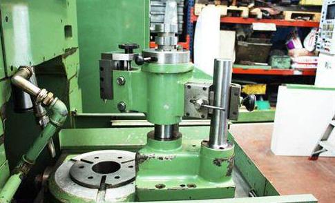
Below is a diagram and a designation of the machine controls:

- Spindle of a grooving tool.
- Coolant supply regulator.
- The fixing nut of the caliper.
- Circular feed element.
- Reversible handle.
- Screw for the longitudinal movement of the caliper.
- Start button.
- Stop key.
- Switch from the setup mode to the working stage.
- Local lighting switch.
- The regulator for the push.
- Block of radial feeds.
- Switching on the radial coupling.
- The main switch.
- Square for manual drive.
- Plank for the reference mechanism.
As you can see, the unit under consideration has a fairly reliable and understandable design, while it is characterized by high productivity and versatility in application.